三極管放大電路三級9V調頻話筒(英文),Three Stage 9V FM Transmitter circuit
關鍵字:三級9V調頻話筒,三極管放大電路
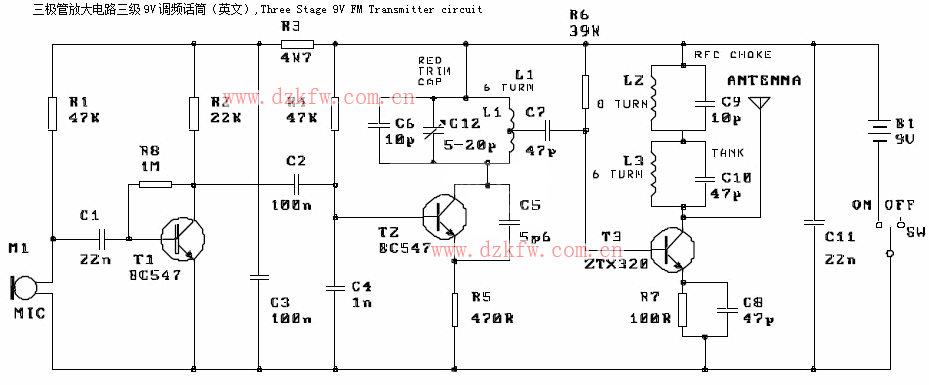
Three Stage 9V FM Transmitter circuit diagram
This circuit is a powerful three stage, 9V FM transmitter (Tx) with a range of up to 1 kilometer in the open. It uses an RF transistor in its output stage and two BC547’s for the first two stages. Distance of trans-mission is critically dependent on the operating Conditions (in a building or out on the open), type of aerial used (single wire or dipole), operating voltage (12V is better than 6V) and if the circuit is peaked for maximum performance.
Components List:
|
Resistors, 5%, 1/4W: |
Capacitors: |
RF transistor ZTX320 – 1 |
The circuit is basically a radio frequency (RF) oscillator that operates around 100 MHz. Audio picked up and amplified by the electret microphone is fed into the audio amplifier stage built around the first transistor. Output from the collector is fed into the base of the second transistor where it modulates the resonant frequency of the tank circuit (L1 coil and the red trimcap) by varying the junction capacitance of the transistor. Junction capacitance is a function of the potential difference applied to the base of the transistor T2. The tank circuit is connected in a Hartley oscillator circuit. The final stage built around T3 amplifies the output RF signal.
Note:
This circuit comes from kitsrus.com and the kit for this circuit is available there.


 返回頂部
返回頂部 刷新頁面
刷新頁面 下到頁底
下到頁底