使用CD4069非門電路制作的調頻話筒(英文),FM Transmitter Using Logic Gates
關鍵字:CD4069,調頻電路圖
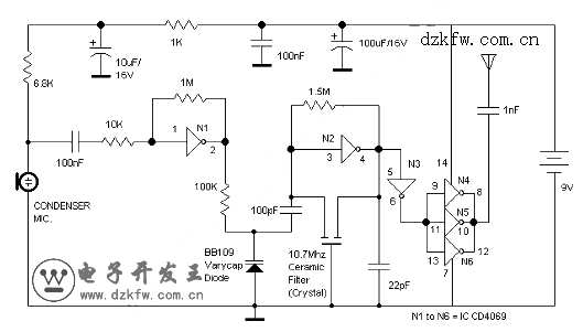
This is a FM Transmitter circuit. This circuit uses logic gates. This transmitter circuit has a RF oscillator. This oscillator uses 10.7Mhz ceramic filter and inverter N2 to drive the parallel combination of N4 to N6 through N3. Here is the circuit:
The output impedance will be low because these inverters are in parallel, so an aerial of 1/4h wavelength can be driven directly. There would be a lot of harmonics in the output of N4-N6 because the output of N4 to N6 is square wave. The 9th harmonics of 10.7Mhz (96.3Mhz) will hence be at the center of the FM band. As an audio amplifier, this circuit uses N1. It will amplify audio signals from the microphone and fed it to varycap diode. The capacitance of the varycap is varied by the signal that will vary the oscillator frequency that produce Frequency Modulation.
這是一個調頻發射機電路。該電路采用邏輯門。該發射機電路具有射頻振蕩器。該振蕩器采用10.7mhz陶瓷濾波器和非門N2驅動并聯組合N6通過N4 N3。這里是電路:
由于這些非門并聯,所以輸出阻抗很低,因此可以直接驅動1/4波長的天線。會有很多諧波在n4-n6輸出由于輸出N4 N6是方波。第九次諧波的10.7兆赫(96.3mhz)會因此在FM頻段的中心。作為音頻放大器,該電路采用N1。它會放大來自麥克風的音頻信號和變容二極管。該變電容的信號,將改變振蕩器的頻率,產生不同的頻率調制。





 返回頂部
返回頂部 刷新頁面
刷新頁面 下到頁底
下到頁底